|
F150 Lightning Specific Instructions
From sources including Ronald
Hampton - ( CLICK TO SEND RONALD AN EMAIL ) Thanks Ronald !!
{Siliver_2000 - (The webmaster)
finally got around to installing the keypad on 9/24/01 and added some more
pictures and detail. All the text I added is in
italics .}
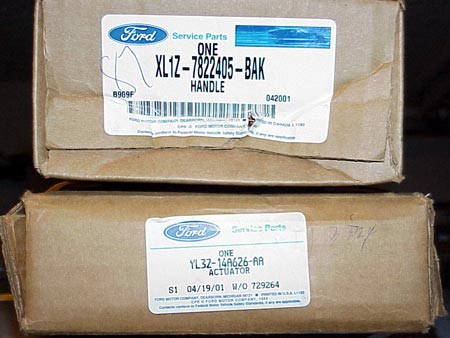
The F150 part # is:
XL1Z7822405DAB is a Red (E4)handle
XL1Z7822405BAJ is a White (Y0)handle
YL3Z14A626AA is the keypad
( Parts Silver 200 ordered for his Keypad )
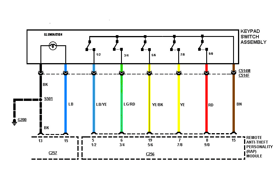
Just completed the install of the Keyless Entry Keypad. I reviewed the
instructions on the Expedition board and printed out the wiring diagram. Then
examined the module on my 2000 L and recognized that the wires were already in
place for the keypad. Went to the dealer and the wiring diagram did show that
the wiring harness was in the door. ( 99 Lightnings will need the wiring harness
for the door )
Do this with the window up at all times.
Remove the door panel by popping off the “sail” panel and the door handle trim.
Both should be removed by hand without the use and any tools. This revealed a
Phillips screw under each one. Remove both screws and lift the door panel up and
it comes right off.
Handle pulls out and the first screw to remove is pictured here
The "sail Panel " pulls off and the
second and final screw is already removed in this picture
Unplug all the wiring connectors from the door panel. Just squeeze the release
button and pull out.
Don't forget to twist the bulb out of
the door panel
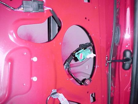
Next remove the speaker and unplug it. Then used a hair dryer to slowly remove
the stuck-on insulation.
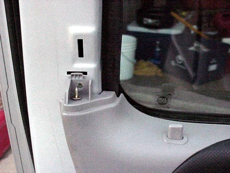
Remove the entire piece. Look into the top right of the speaker hole and you
will find the mysterious plug for the keypad.
( Note: I was able to do the mod without pulling all the
stuck on insulation - Silver_2000 )
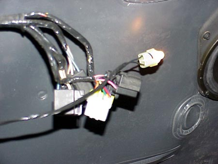
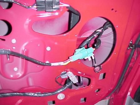
Push the 2 small white clips and the plug comes right out.
Mine had a plug in the end of the Keypad
harness that I had to remove
In my excitement knowing that I didn’t have to go through the nightmare of
completely wiring the keypad, I plugged it in for an immediate test.
I looked at the white control module (RAP – Remote Anti-theft Personality) and
got my access number. Keyed in the 5 digit and then came the big smile on my
face. All features worked.
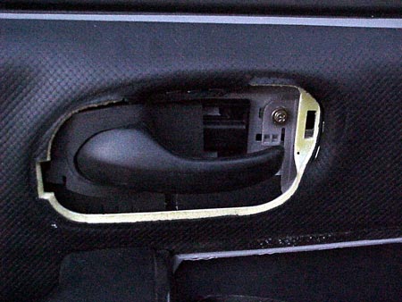
The next step was to remove the handle. I
used a 10 MM socket to get the right nut off. The left nut was real difficult to
remove. The connector rod between the handle and the locking mechanism was
directly in the way. I used a universal joint for my ¼ “ socket driver and
eventually was able to get it off. Using a 3/8 or ½ socket driver will be too
large as there is not much room in there. Might give it a try though if that is
all you have. The nuts were not 3/8 inch. A 3/8 inch socket could possibly work
but there is a threat of rounding off the nut.
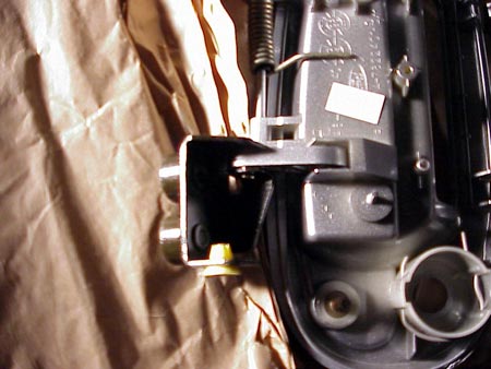
I also loosened the bolt holding the left
window channel to the door. Lower left corner of the below photo. This helps to
get around better to get the left nut off.
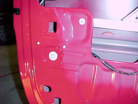
MAJOR HINT: look at the below photo and you will see a yellow clip that is
holding the connector rod to the locking mechanism. The clip can be opened and
the rod will come right off.
I used a small screwdriver to pry the flat clip towards me. Then
it can be removed from the handle. This will make it real easy to get the left
nut off. I didn’t do this until I had gotten the handle off. Since this part is
threaded, I didn’t know if the clip came off or if the rod was screwed in. The
clip does just hold it in. The threads are to make sure it does not slip up and
down.
Before removing the handle, I surrounded
the entire area with duct tape so the handle would not scratch anything. Good
thing as it is real tight getting the lock clip out of the handle assembly
I then removed the handle by pushing the lower part out far enough to get the
clip loose that holds the door lock in. Used a pair of channel locks to pull the
U shaped pin out. The lock then fell out and I removed the small rod that
connects it to the locking mechanism. Only remove the rod from the lock itself
and let it dangle inside the door.
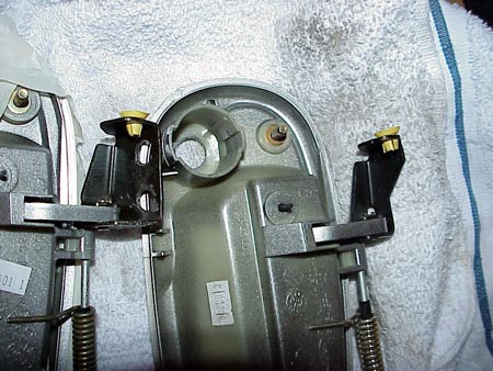
The picture of the boxes at the top are
the parts I bought based on the part numbers here. If you look at the
picture above you will see that the handle now has two counter weights and a
wider bracket that have to be modified to fit my 2000.
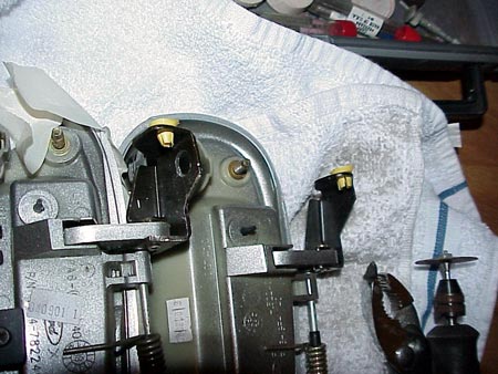
Here you can see the handles side by
side. The one on the left is the new one with the counterweights drilled off but
you can see the bracket is shaped different than the stock handle on the right.
In this picture you can see what 5
minutes with a Dremel cut off wheel does. With the bracket cut like this
the handle will fit back in the door. Don't try to force the handle before
you modify the bracket. The handle is mostly plastic and will break.
Next step was to install the lock and
keypad on the new handle. Put the lock back in the handle and secure it with the
U shaped pin that holds it in. DON’T put the connector rod for the lock back on
yet. This can be done after the new handle has been bolted in. Attach the keypad
to the handle (one screw). My keypad did not come with a screw. Be careful with
the size and length of the screw you use since this is plastic and if you crack
the hole opening YOU are screwed and not the handle. Check with you dealer and
see if he shows a part number for the screw.
Feed the keypad wiring through the door
handle hole and put the handle in the door. Don’t connect the rod for the handle
at this time. In fact, if you removed it to get the left nut off it should be
completely out of the door. Connect the plug and test it. Pressing the 7/8 9/0
together to lock the doors and key in your 5 digit code to unlock them. Then
unplug it. Since there is no bare wires to contend with, it is not necessary to
disconnect the battery for this install.
Put the 10 MM nuts back on. Might want to
get someone to hold the handle in place from the outside of the door. It moves a
little so they can keep it centered. After the handle is secured, secure the
keypad wiring harness inside the door. On your wiring harness you will see 2
white clips. These are to hold it in place inside the door. Believe it or not,
there are 2 openings in the very top of the door area. Look all the way to the
top and you will see 2 oval holes 11 inches apart.
( There are holes are in the bottom of the window channel all the way at the top
of the door to attach the cable. IT keeps it out of the way of the window
- I couldn't see them but in amongst the grease I could feel them. The
harness leaves the handle goes up along the top of the door on and down to the
speaker hole. ) em in. If they are a little off just untape the clips and
move them enough to plug in. I had to move the one closest to the handle about
3/8 inch so it would plug in.
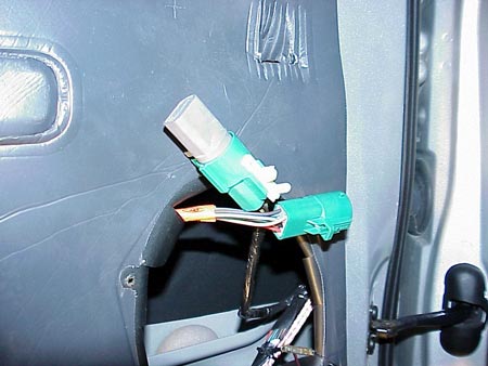
Make sure the plug assemble goes behind the
window channel DUH! Plug that sucker in and you are about done. Test it again.
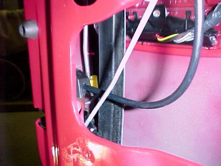
With my keypad assembly, the wires were not long enough to secure the plug back
to the door with the 2 white clips. I folded the excess wires and taped them
together with duct tape. See below.
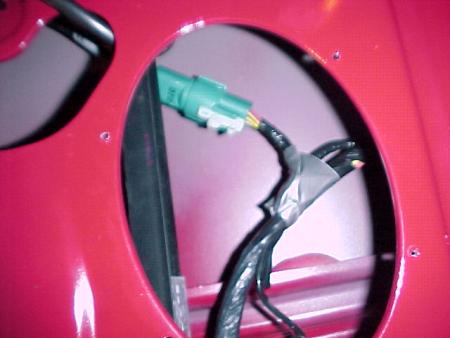
Sorry about the blurred picture.
Now connect the door handle rod to the
handle and place the threaded end back on the door lock mechanism and pop the
yellow clip back in place. Also, just push the door lock connecting rod onto the
lock in the handle.
You are done with the keypad part. Do a final test and put the door back
together. Here’s what mine looks like.
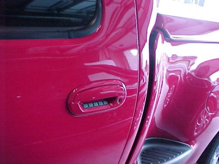
Silver_2000's Keypad
If you want these instructions without the
photos e-mail me.
It took me 3 hours to do this install. It took me 2 hours to get the left nut
off. With these instructions you should be able to do this in about 1 hour. The
biggest trick is to remove the yellow clip on the door handle connector rod and
removing the window channel bolt.
Album of photos at
Click here to see album
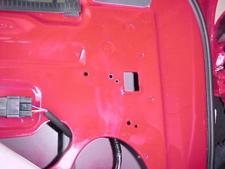
I went back into my door and make a modification that will allow the 2 clips on
the plug to attach to the door in the same manner it was before the install. To
view my keypad install photos go to my album at -
Click here to see album and view the bottom 2 photos and note that the 2 new
holes are just to the left of the rectangular opening.
( I didn't have to drill any holes the
two holes right above the speaker hole are what the harness was plugged into and
mine went back into it just fine )
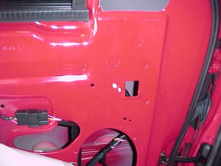
I had to drill 2 holes about 6 inches from
the old ones at the eleven o'clock position. The larger hole is 1/4 inch and the
smaller one 3/16. Since the new hole will be rougher than the original factory
hole it will be necessary to ream the hole out a little to get the clips to pop
in.
If you do this mod take extreme caution
when drilling so the bit does not get pulled through the hole and into the outer
door surface. As soon as the drill bit breaks through it will have a tendency to
corkscrew into the hole. BE CAREFUL. And yes, I was able to stop the drill bit
once it started to corkscrew through the hole.
Toyman
------------------
2000 Lightning - Red
Superchip CUX2R7
Airaid Filter
ARE II Hard Cover
2" Aim Drop Shackles
G-Tech
Dual 40 Series Flowmasters
1998 Lincoln Mark VIII - Black
1988 Jeep Commanche 4X4
e-mail addr
rhampton@mindspring.com
"He who dies with the most toys WINS
http://www.f150online.com/forums/showthread.php?s=&threadid=25917
The one thing that I had trouble with was how to route the cable in the door so
that it would reach to the connector and not be anywhere near the window
mechanism parts. I can't figure out how some of the others were able to do this
so easily. I know the harness is supposed to be a few inches short but mine
seemed to be about 5 inches too short even for the method suggested by ToyMan. I
had to really rig the cable and remove the sheathing and cable tie it to the
inner door.
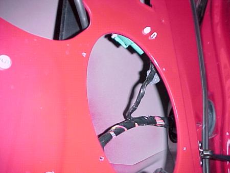
So, my cable goes from keypad around the
window guide immediately in front of the keypad (so now the cable is effectively
in front of the window towards the inner door opening) cable tied along the
inside of the door skin, stretched to the connector. Bottom line, it's cool,
looks good, and works great...
( There are holes are in the bottom of the window channel all the way at the top
of the door to attach the cable. IT keeps it out of the way of the window
- I couldn't see them but in amongst the grease I could feel them. The
harness leaves the handle goes up along the top of the door on and down to the
speaker hole.)
paint codes:
silver - YN
red - E4
black - UA
white - YO
ford locking gas cap - $19.90
XY5Z 9030 FA
the Y may have been a 4, try both.
keypad - $72
XL3Z-14A626-AA
YL3Z-14A626-AA
door handle - $50
XL1Z-7822405-BAK silver (YN)handle
XL1Z-7822405-DAB red (E4)handle
XL1Z-7822405-BAJ white (Y0)handle
XL1Z-7822405-BAH black (UA) handle
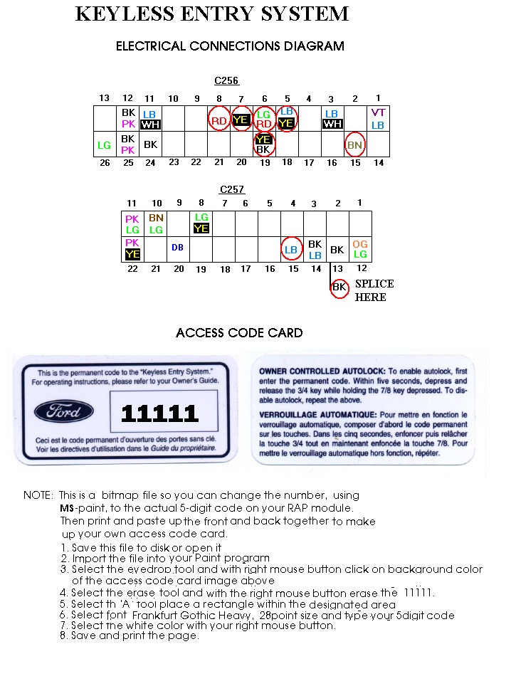
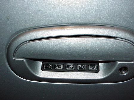
Your vehicle has a factory-set 5-digit code that operates the keyless entry
system. The code is located on a sticker on the computer module (RAP). When
pressing the controls on the keyless entry keypad, press the middle of the
buttons to ensure a good activation.
How to set your own personal entry code or Open
Both doors or disable autolock
IMPORTANT: Every step outlined in
every procedure below must be done within five(5) seconds of the previous step.
Programming your own personal entry code
Enter the factory-set code (keypad will illuminate when first digit is pressed).
Press the 1/2 control.
Enter your personal 5-digit code.
Your personal code does not replace the factory-set code. You can use either
code to unlock your vehicle. Each time you set a new personal code the module
will erase the previous one in favor of the new code.
Deprogramming (erasing) your own personal code and leaving only the
factory-set
Enter the factory-set code.
Press the 1/2 control.
Press the 7/8 and 9/0 controls at the same time.
The system will now only respond to the factory-set code.
Unlocking the driver's door (also disarms the perimeter alarm system)
Enter either the factory-set code or the personal code. The interior lights will
illuminate as soon as the first valid digit is pressed.
Unlocking all doors - Unlock the driver's door then press the 3/4
control.
Locking the doors (also arms the perimeter alarm system) -Press 7/8 and
9/0 controls at the same time. The 5-digit code does not have to be entered.
Deactivating/Activating Autolock - Enter the five (5) digit code.
Press and release the 3/4 control while holding the 7/8 control, then release
7/8.
|